CD and DVD Solar Spectrograph
Using a Compact Disk (CD) and a Digital Versatile Disk (DVD) to record the Fraunhofer lines of the solar spectrum
by Joe Gerencher . . . . . . . email address: gerencher@moravian.edu
For my webpage about my homemade prism star spectrograph, click the following link: Stellar Spectra - Telescope
For clarity in these webpages, I will use the following as my definitions of spectroscope and spectrograph: a spectroscope is a device that allows a person to see a spectrum, whereas a spectrograph is a device that also allows a person to record a spectrum.
Part 1 of 11: Overview of the Solar Spectrograph using the CD
The images that follow on the first part of this webpage show my homemade solar spectrograph that is made with a compact disk (CD), which serves as a diffraction grating. The Digital Versatile Disk (DVD) version of this spectrograph is covered in Parts 4 and 5.
The image below shows the spectrograph set up in my back yard for a noontime observation of the sun.
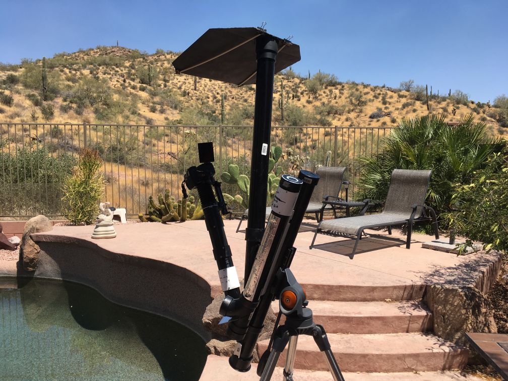
On all subsequent images, the solar spectrograph will be shown set up on the driveway of my front yard, which has a good elevated view of the western horizon.
On the image below the spectrograph is oriented pointing to the left.
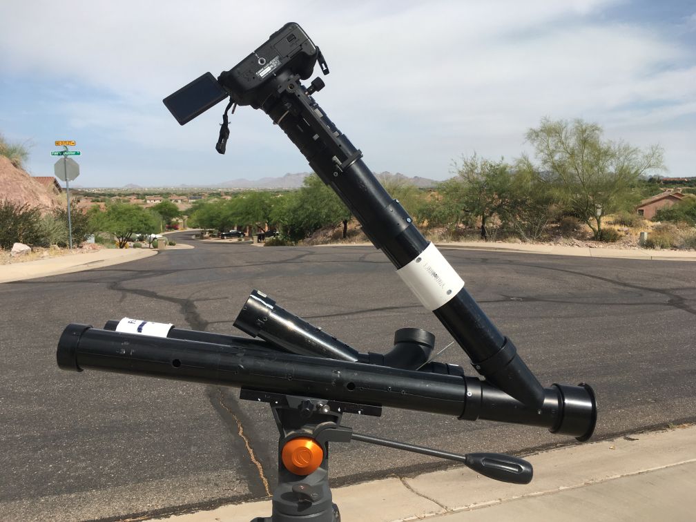
On the image above, there are two parallel, two-inch diameter, black plastic plumbing tubes (pipes) that are almost horizontal, the nearer of which is the spectrograph, and the one more distant is the sighting device. The two white plastic couplers in the picture each contain a simple converging lens that will be described in a later part of this webpage. The short black pipe that is angled up from the two horizontal pipes (over the tripod connection in this image) is provided to support the cardboard sheet that protects the camera with its shadow (shown in the first image).
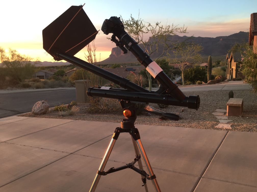
On the image below, the device is oriented pointing to the right. The near-horizontal tube closer to you is the sighting device which consists of a simple converging lens at the open end (right side) and a plastic mirror mounted at a 45 degree angle which projects the sighted image onto a translucent plastic viewing screen that is horizontal in this image.
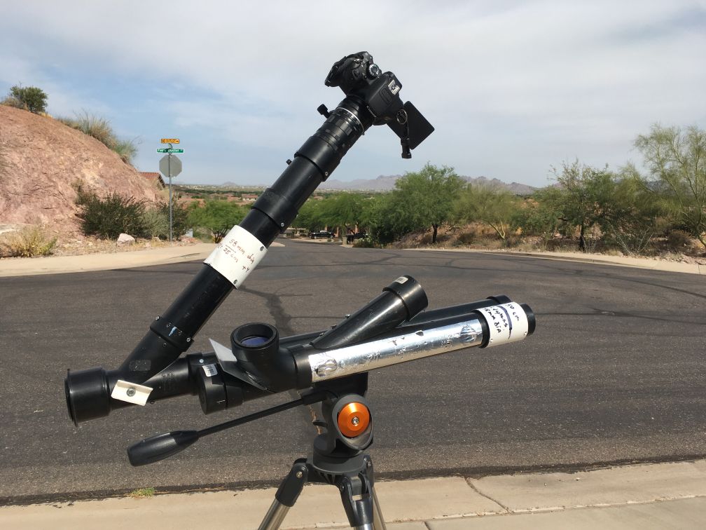
On the image above the inclined black tube supporting the Canon T4i digital camera is the spectrograph in which the diffraction grating is located at the junction of the horizontal and inclined tubes and is attached to the threaded rod that has the white handle. Using the white handle to slightly rotate the threaded rod reorients the diffraction grating. In this device, a disk-shaped piece of compact disk (CD) about 45mm (1.75 inches) in diameter is used as a diffraction grating.
On the image below, the spectrograph is pointing at you. The left horizontal black tube is the sighting device and the right one is the spectrograph itself. The front end of the spectrograph contains the slit device, which will be further described in subsequent portions of this webpage.
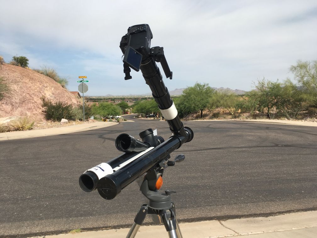
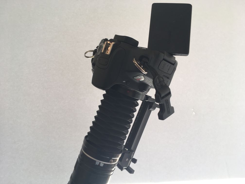
The above image shows the Canon T4i digital camera mounted on a Canon camera extension bellows which I inexpensively obtained online from eBay. There are also Canon extension tubes below the extension bellows to allow convenient modification of the placement of the camera when adjusting the focus. The threads of the extension tubes also allow easy rotation of the camera to permit the reorientation of the spectrum to match the long dimention or short dimension of the camera sensor.
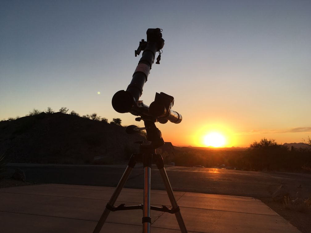
On the image below, the spectrograph is pointing at the setting sun. Imaging the solar spectrum at this time of day provides a strategy for managing the otherwise overwhelming brightness of the sun without using solar filters, which themselves may affect the spectral results being sought.
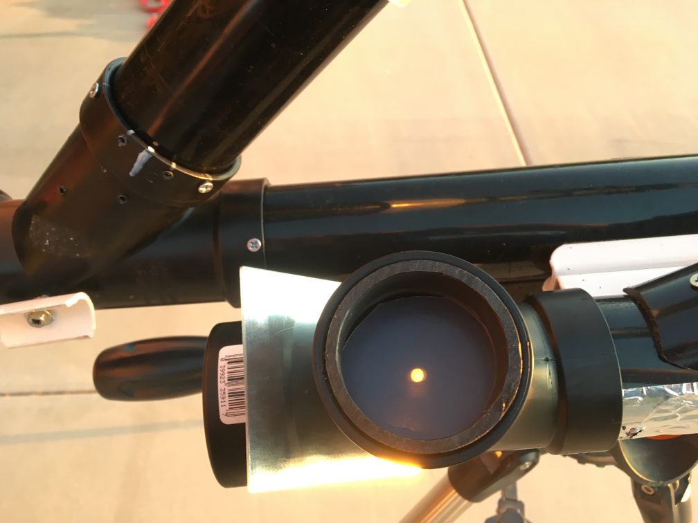
The photograph below shows the screen of the pointing mechanism with the image of the setting sun taken moments after photographing the above image. The screen is a piece of translucent plastic cut from a sheet of a 12-inch by 15-inch kitchen counter surface protector. Not shown in this picture (but shown on the first picture of this webpage) is a cap with a tiny hole placed on the open end of the sighting device to reduce the intensity of the sun's light so it does not melt the plastic mirror and/or the translucent plastic viewing screen. The plastic mirror was obtained from a science supply company that produces educational materials that are typically used in elementary schools. Such mirrors can be easily shaped with hand tools.
Extension bellows for the Canon T4i digital camera body provide the ability to focus the camera on the Fraunhofer lines while watching in "Live View." The screen on the Canon T4i camera can be easily positioned to provide a convenient view, which is essential for some orientations of the spectral apparatus. It is also helpful that the camera settings and the camera shutter can be controlled from the touch screen.
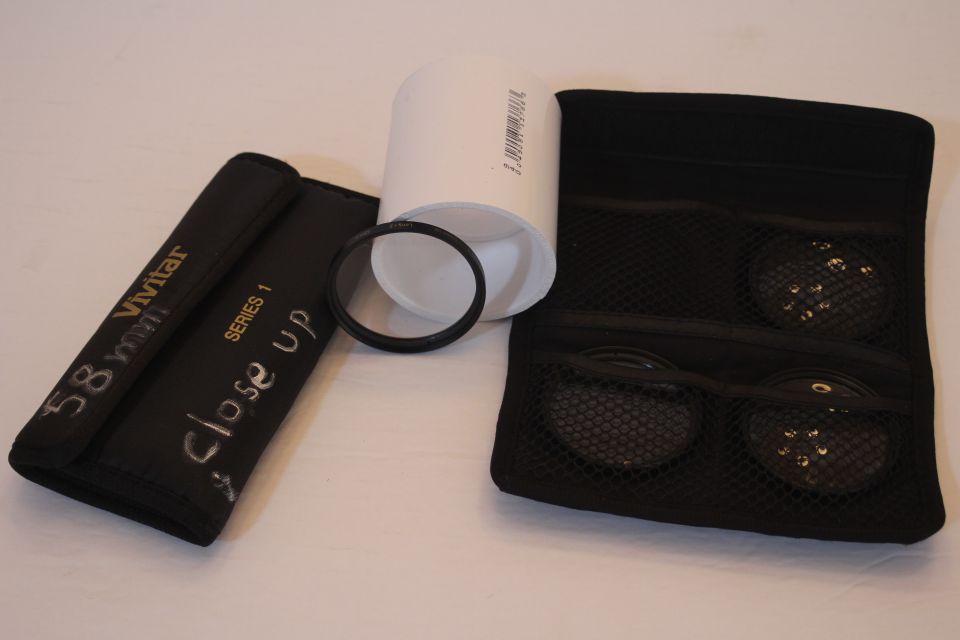
Between the camera and the compact disk is a 4X (4 diopter) lens which has a focal length of 1/4 of a meter, or 25 centimeters (approximately 10 inches). The lens has a 58 mm diameter, which is almost exactly the interior diameter of the white plastic coupling. A similar white plastic coupling is positioned at the end of the aiming tube and likewise holds a 58mm diameter lens, but this lens is a 2X (2 diopter), so it has a focal length of 1/2 meter, or 50cm (approximately 20 inches).
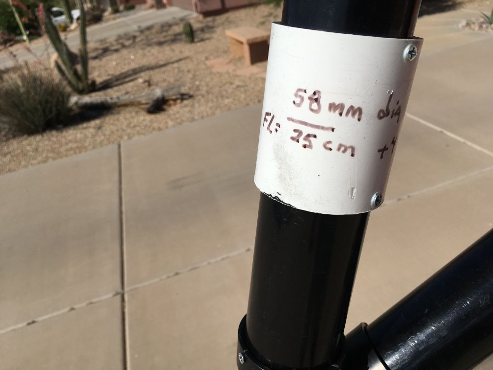
The lenses are part of a 58 mm set of simple magnifying (close-up) lenses for standard cameras. I obtained sets of magnifying lenses inexpensively from eBay.
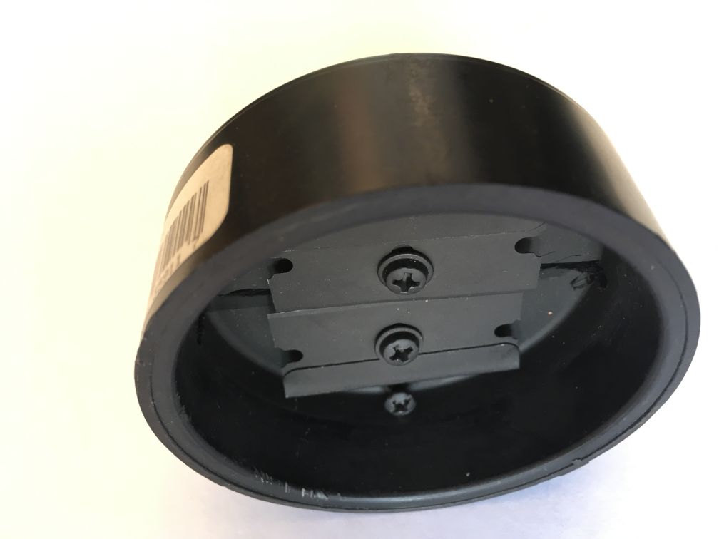
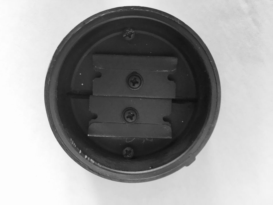
The slit is made of two single-edged razor blades that can be slightly adjusted. Two views of the same slit are shown.
A circular piece of the compact disk, approximately 45 mm (1.75 inches) in diameter, is mounted on a small piece of a plastic plumbing part and is attached to a long threaded rod that extends from top to bottom of a "Y" fixture, with a handle on one end so the compact disk can be rotated about the threaded rod. The view here is seen down the straight segment of the "Y" fixture.
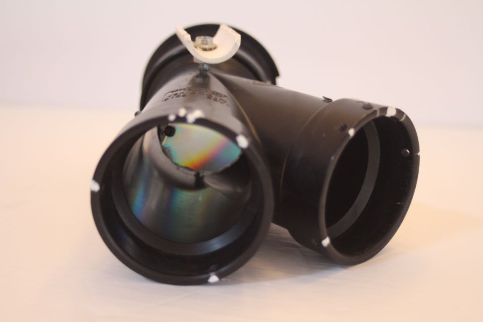
The view below is down the bent part of the fixture.
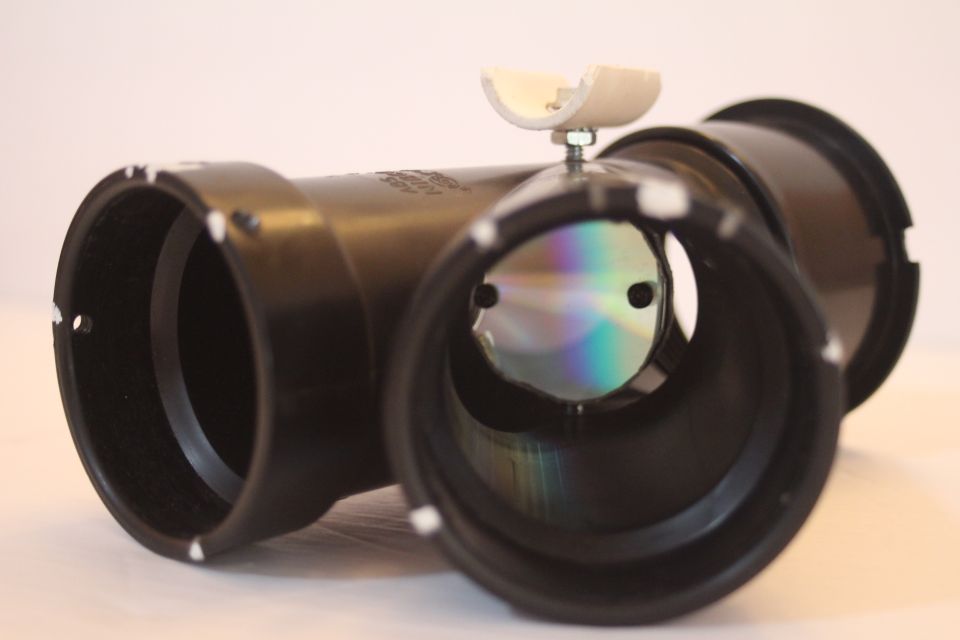
The end is usually capped with a threaded black plastic block, but that has been removed to make these pictures.
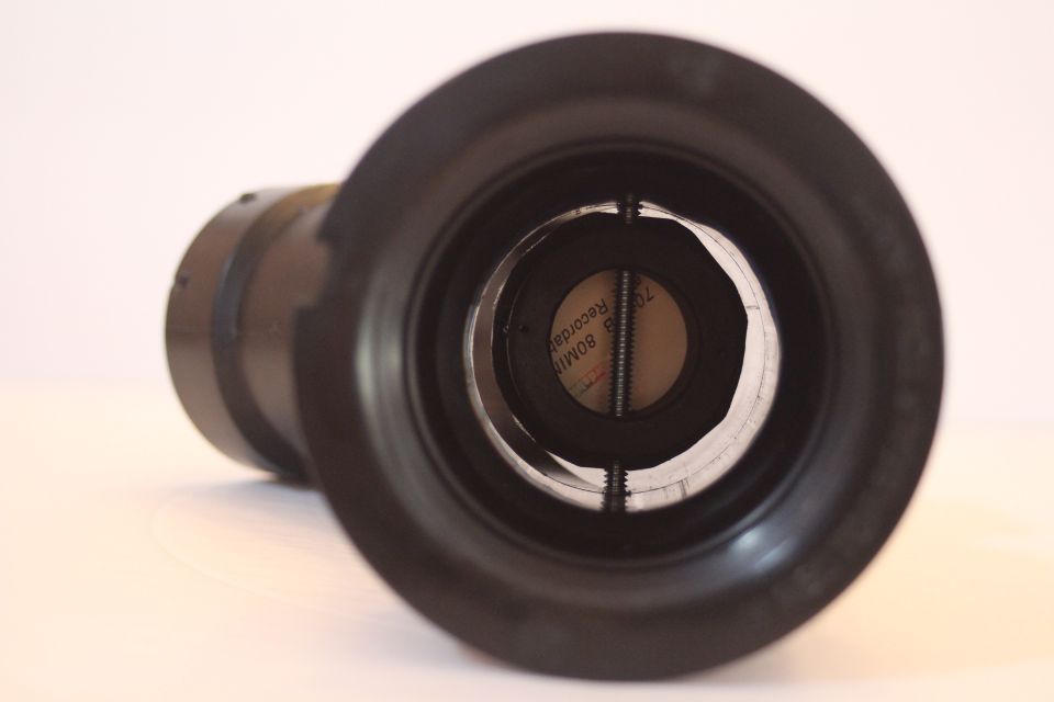
The view below shows the two different paths in the plastic fixture.
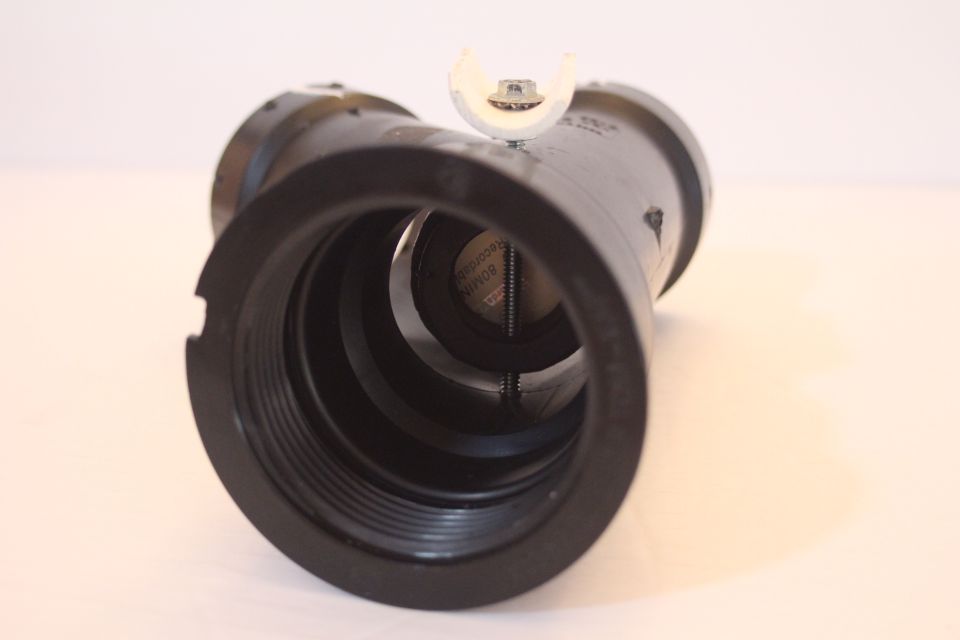
The essential measurements for the separations between the major components of my spectrographic system are as follows: distance from the slit to the diffraction grating (CD or DVD) is 70 cm (27.5 inches); from diffraction grating to the 4X lens is 26 cm (10 inches); from the 4X lens to the start of the extension tube set is 24 cm (9.5 inches). The first ring (a thin ring) of the extension tube set is glued onto the end of the black plastic pipe so that it is fixed in position, but all subsequent rings are removeable. The bellows is attached to the upper-most ring of the extension tube set via the camera adaptors that are supplied with these sets and are specific to the manufacturer of the camera and the model of the camera. I positioned the 4X lens to have its convex surface facing away from the camera, similar to the orientation it would have, relative to the camera body, had there been a camera lens present on the front of the camera (there is no such camera lens in this setup).
Part 2 of 11: Using the CD Solar Spectrograph on sunlight reflected from the full moon
Below are five sections of the solar spectrum which were obtained by imaging the sunlight reflected from the full moon. The moon was treated as a gray mirror in an effort to make the solar image less bright.


For the image below, the above five images are arranged in order to show the amount of overlap and the continuity of the lines in the overlap regions.
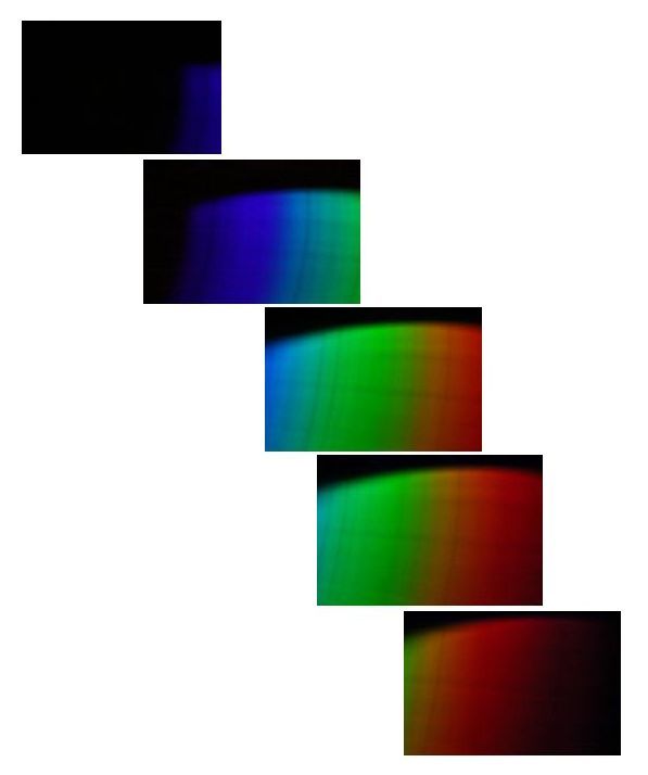
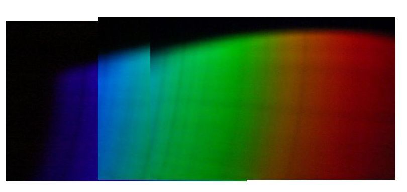
On the image below, the five previous images have been stitched to show the complete solar spectrum in the visible range (or more accurately - the range of the sensor of the Canon T4i camera). The vertical dark lines in the spectrum are the Fraunhofer lines. These lines are caused by atomic and/or molecular absorption in the solar atmosphere and/or in the Earth's atmosphere.
------------------------------------------------
Part 3 of 11: Using the CD Solar Spectrograph on the setting sun
I photographed the spectrum of the setting sun in an effort to optimize the absorption effects produced by the Earth's atmosphere. The light path through the lower regions of the Earth's atmosphere, where the air density is highest, is maximized during these circumstances. The Fraunhofer features associated with absorption by the Earth's atmosphere are referenced as "Telluric" lines or bands (Fraunhofer A and B bands).
The images that follow were taken a few days after summer solstice in 2019, late in the afternoon as the almost-setting sun was slightly above the western horizon. Because I live near the very eastern edge of the Phoenix, AZ, metropolitan area, the path of the light is through a majority of air that is at a low altitude above a large urbanized region.
The cardboard screen provides shade to the camera and reduces the problems with viewing the "Live View" image on the screen.
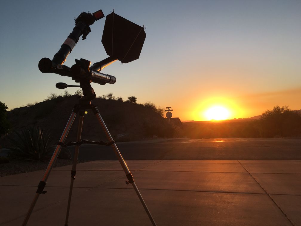
The view below shows the position of the cardboard sun blocking screen. To image the setting sun, the spectrograph and sighting tubes are almost horizontal.
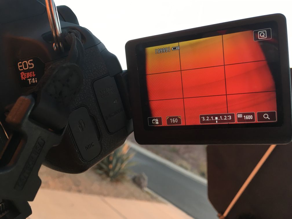
The picture below shows the red portion of the solar spectrum as it appeared in "Live View." The spectrum is wider than the APS-C sensing chip of the Canon T4i digital camera so several successive images are taken and are later stitched together to form a more complete composite view.
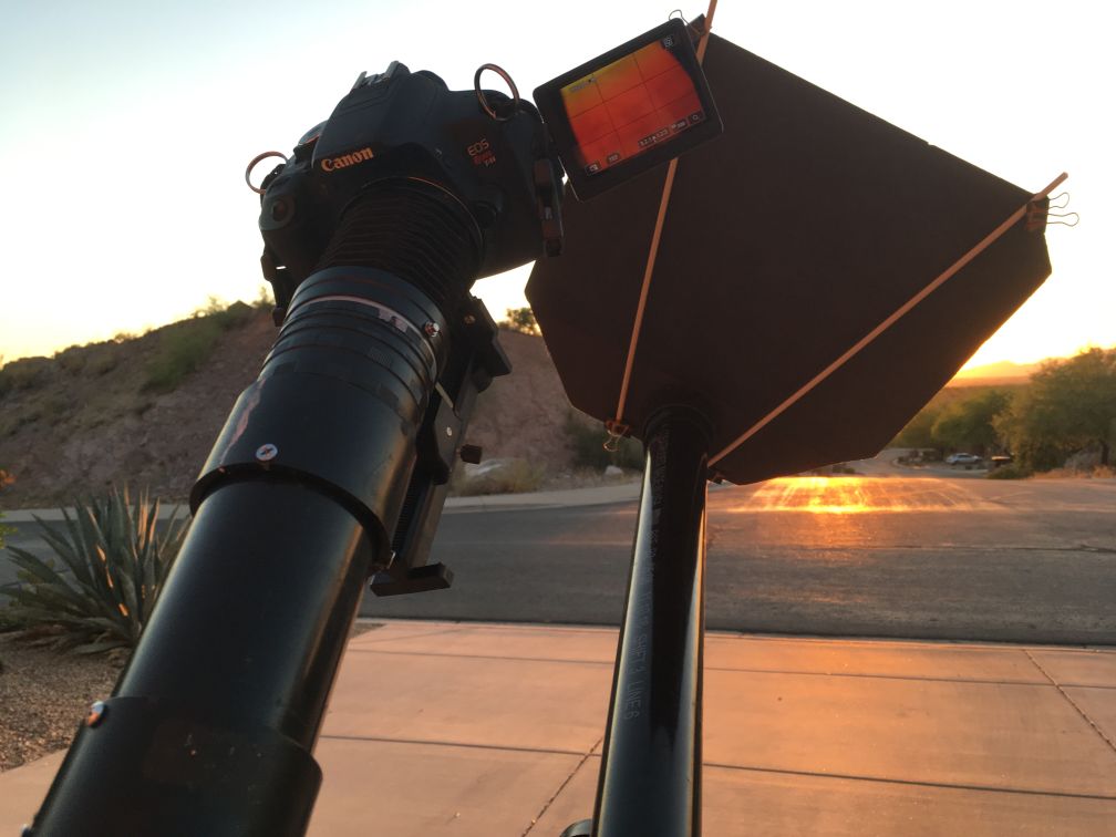
The picture below shows a more detailed view of the camera screen. When imaging the setting sun, the amount of light diminishes quickly, so the exposure has to be adjusted several times.
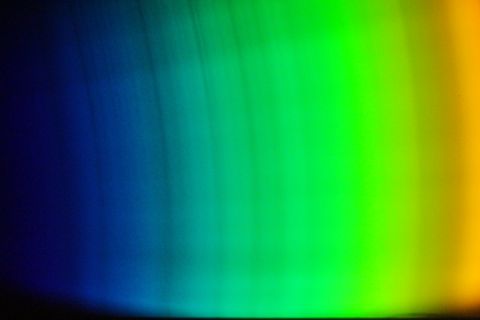
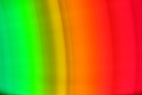
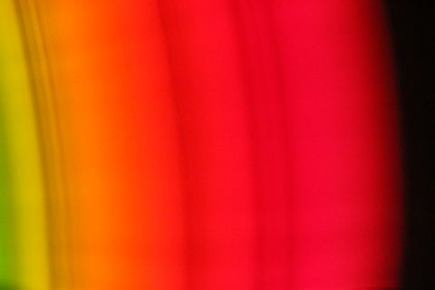
Presented below are three images of the complete solar spectrum near sunset. The major Fraunhofer lines are readily apparent. The exposure setting for these images was 1/160 second at ISO 1600.
Below is a stitched composite of a series of three images, using the same exposure settings, that were taken about a minute before the three separate images above.

Below is a stitched composite of three images that were taken about a minute after the three separates, when only a small fraction (less than half) of the setting sun was exposed above the distant horizon. The exposure settings for this composite image were 1/8 second at ISO 6400. The sun's light was decreasing rapidly, so I selected these camera settings to allow more light to fall on the sensing chip than the previous settings.

Notice the Fraunhofer lines on the solar spectrum are arcs rather than straight lines, probably resulting from the arcing of the tracks on the section of the compact disk that was used as a diffraction grating. This is simply one of many limitations in trying to use common black plastic pipe with shiny internal surfaces, common simple lenses which are not corrected for chromatic aberration, a slit made from straight- edged razor blades, and cut pieces of a compact disk to obtain the Fraunhofer lines of the solar spectrum. The surprise is that it works at all.
---------------------------------------
Part 4 of 11: Substituting a DVD for the CD in the Solar Spectrograph
Could a DVD be used instead of a compact disk (CD)? Yes! To pursue this question, I cut a circular section from a DVD and substituted the DVD for the CD.
The CD and DVD can be cut into disks with substantial scissors. The metallic surface of the CD is sandwiched between two layers of plastic, but the metallic surface of the DVD has a very thin layer of blue liquid separating its thin metallic layer from one of the two outer plastic layers. This allows that outer plastic layer to be easily removed, exposing some of the blue liquid, which can be washed off the metallic surface by rinsing it with rubbing alcohol. Because I did not know the chemical properties of that blue liquid, I used medical examination gloves when cutting the DVD with the scissors and rinsing the DVD disk with rubbing alcohol, and I used only workshop scissors that would never be used for any food preparation. The cut CD and DVD disks are shown below.
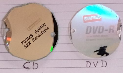
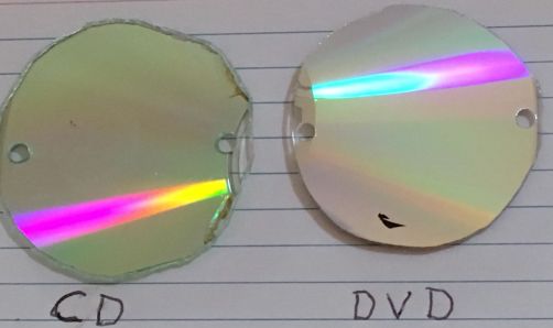
I used the DVD in the now-modified device to obtain the spectrum of the mid-afternoon sun. The resulting spectrum was more spread out because the grooves are more closely spaced on a DVD than on a CD. Below are three examples of full-frame images using the DVD.

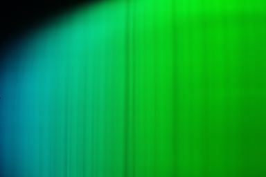
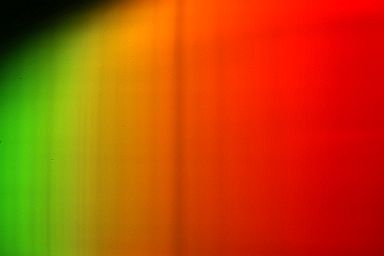
Thus, the resultant spectrum required 10 separate images to record the whole visual range, whereas 3 images will usually suffice when the CD is used as the diffraction grating. See the composite spectrum below which was made with the DVD.

The solar spectrum above, taken with the DVD as the diffraction grating, contains more detail than the spectrum taken with the CD. However, both suffer from a lack of contrast between the colored background and the lines on that background, particularly the very thin lines.
There is an important difference between a CD and a DVD that influences the effort: the metallic reflecting material in a CD has plastic on both sides, even when cut as a spectrograph disk, whereas a cut disk made from a DVD has the surface of the bare metallic material now exposed to the air. This exposure causes the metallic surface of the DVD to slowly tarnish, and this slowly darkens the surface and degrades the performance of the DVD. Based upon my experience, a diffraction grating made from a DVD should be replaced every three months to six months.
Shown below are two images of 3X5 cards which have DVD diffraction gratings on them. These gratings are made from cut pieces of unused DVDs for a prototype of my spectral device that I made about two or three years previous. Notice the exposed metallic surfaces are now very tarnished.
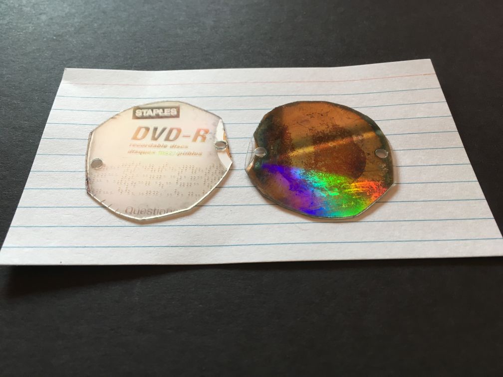
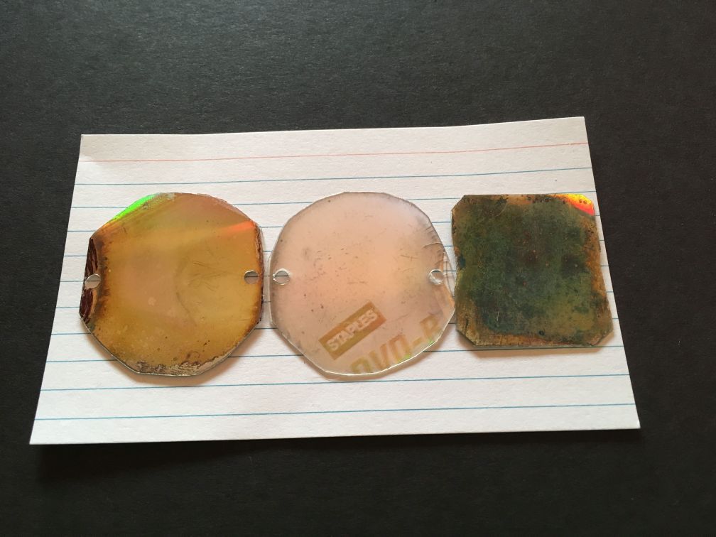
On each of the images above, one DVD diffraction grating is tarnished-side down; the others are tarnished-side up.
-------------------------------------
Part 5 of 11: Improving the contrast of the DVD Solar Spectrograph
The 2-inch diameter plastic pipes used in making the spectrograph are black in color, which would be expected to absorb stray light within the interior of the device, but their interior surfaces are very smooth and reflective for light that strikes their sides at low angles. Incident light striking the diffraction grating (whether a CD or a DVD) at an angle from the normal (the "normal" is a conceptual line perpendicular to the surface) has its largest component that is reflected at the same angle on the other side of the normal. Light striking the diffraction grating also produces bands of color (the first order spectrum) on both sides of the incident beam, with only one of these two color bands entering the camera. Thus, there is a large percentage of the admitted sunlight that bounces around the interior of the spectrograph, and, if this stray light ultimately enters the camera, it diminishes both the pure colors of the spectrum and the contrast between the background spectral colors and the absorption lines.
Based on the assumption that the low contrast of all the previous spectral images resulted from reflections throughout the interior of the black plastic pipes from which the spectrograph was made, I embarked on an effort to absorb the stray light by painting all internal surfaces with flat black spray paint and by applying glue-backed black felt materials on those interior surfaces that I could reach after dissassembling the entire device. The improvements were immediately obvious. See below for full-frame examples.


-------------------------------------
Part 6 of 11: My early solar spectrograph with a commercial high-quality diffraction grating
I previously made a scaled-up version of this device to obtain the Fraunhofer lines of the solar spectrum, but that device was equipped with a high-quality commercially produced diffraction grating which I obtained by bidding on eBay. The price was low because all of the specifics of the grating were unavailable. Fortunately, the grating seemed to be well suited for the task, although its larger size required the use of some components that were also necessarily larger than the 2-inch diameter pipe that was used on my compact disk device. Here is a link to my solar spectrograph device that uses this high-quality, mirrored, commercial diffraction grating: Solar Spectra
-------------------------------------
Part 7 of 11: Illustrated history of the CD/DVD Project, its precursors and extensions -- arranged in roughly topical and chronological order
In this section, I have assembled links to the web pages that I created to document my activities and results, both successes and non-successes, as I experimented with optical materials that had potential for astronomical applications. All of these were done following my retirement from the faculty of Moravian College in 2009.
7.4. Solar Spectra ..... diffraction grating ..... slit
7.5. CD and DVD Solar Spectrograph (this page)
7.6. Blue Sky Spectra ..... diffraction grating ..... slit
7.7. Light Sources ..... prism ..... slit and slitless
7.8. Lightning ..... prism and diffraction grating ..... slitless .......... Variations of some of the same equipment were used to image lightning strokes, so although it is not an astronomical topic, the link to this page is included here.
7.9. Diffraction Grating Versus Prism ..... prism and diffraction grating ..... slit and slitless ..... a selected comparison of linear versus non-linear spectra
---------------------------------------------------------
Part 8 of 11: Non-solar applications of the CD and DVD Solar Spectrograph.
Is it possible to use the CD and/or DVD spectrograph to obtain stellar spectra? For all the spectra on this webpage, I have used only static (non-motorized) mounts, but for attempting to image a star's spectrum, a motorized tracking mount might be necessary. I have suggestions for those who may want to make such a CD/DVD spectrograph and use it to try photographing the spectra of stars.
The effective aperture of the apparatus is only 45 mm (1.75 inches), so the amount of light available to the grating is very limited. Of that light, only a very small percentage is diffracted toward the camera sensing chip. Some of that diffracted light may form a spectrum that is wider than the camera sensing chip, so that portion of the spectrum may not contribute to the image being formed. I suggest developing techniques using a bright planet, which is not a true point source, but that won't make much difference on the scale of the apparatus. Sunlight reflected from a bright planet would be expected to generate primarily the absorption lines in its spectrum of a G2V star because that is the spectral type of our sun.
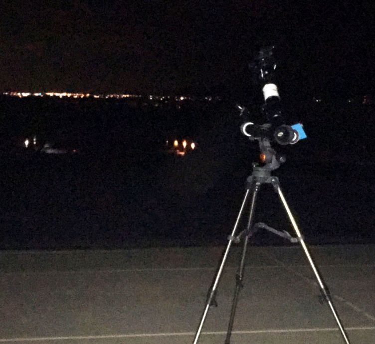
The image below shows my solar spectrograph set up on my driveway with the main tube pointed at the city lights of Apache Junction and eastern Mesa, AZ.
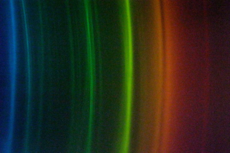
The image below shows the spectrum of the city lights that I recorded using the CD as the diffraction grating. I used these lights to ensure that the device was properly aligned and that the camera was placed at the focus of the scene. Notice that the many different types of lights (fluorescent, LED, sodium vapor and incandescent) make a combined spectrum rather than several individual spectra of the individual lights.
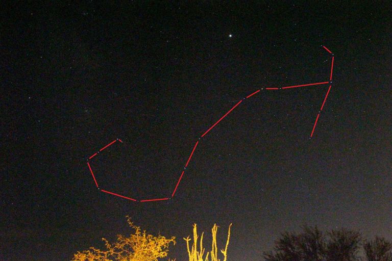
The image below shows the constellation Scorpio. with the planet Jupiter as the brightest object located above it. At the moment when I took this picture, Jupiter had an apparent visual magnitude of -2.28, which is brighter than the brightest star, Sirius. Sirius has a constant apparent visual magnitude of -1.46.
The two following stacked images were made of the planet Jupiter using my CD spectrograph.

The above image is a stack of 10 separate images of the spectrum of Jupiter, each of which had an exposure of 7 seconds at an ISO of 12800. The stacking was corrected with 4 dark frames.
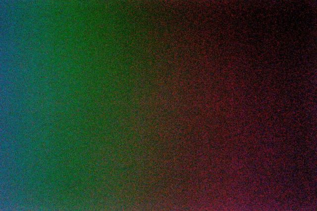
The image below is a stack of 11 separate images of the spectrum of Jupiter, each of which had an exposure of 15 seconds at an ISO of 12800. This stacking was also corrected with 4 dark frames.
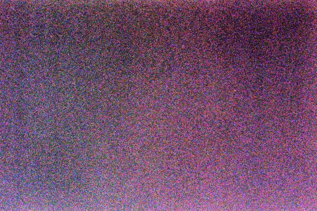
The above two images successfully show the color separation of the CD diffraction grating: the blue is on the left and the red on the right. However, the spectra only make a slight suggestion that there are vertically oriented absorption lines on this continuous background.
The CD spectrum below, taken with my CD solar spectrograph, shows the spectrum of the brightest star, Sirius. It is a singular 10 second exposure taken at an ISO of 12800. Stacking this image with 7 others and correcting it with 4 dark frames did not reveal any of the hydrogen Balmer lines (alpha, beta, and gamma) that should be strongly evident in this A1V spectral type star.
To take these images of point sources (the star Sirius) or nearly-point sources (the bright planet Jupiter), I did the following:
1. I used the CD, not DVD, for the diffraction grating because the dispersion is less and the image is smaller and, therefore, brighter
2. I tried it first on a bright planet and graduated to a star, using the brightest star (Sirius) first
3. I removed the slit
4. I added an extra length of tube to the front of the apparatus to better reduce the field of view and isolate the intended subject of the image
5. I moved the focus inward to 1 focal length distance (25 cm) from the +4 lens
6. I drilled a small (1/8 inch) hole near the center of the CD to use as a peep hole to align the planet or star in the center of the visual field of the now-lengthened tube
7. I took several exposures and some dark frames to stack during image processing
8. What I have yet to try is to mount the apparatus on a motorized tracking drive or in tandem on a tracked telescope
---------------------------------------------------------
Part 9 of 11: The Fraunhofer Spectrum of the Blue Sky
On a cloudless afternoon, I pointed the Solar Spectrograph with the CD as the diffraction grating to a portion of the featureless blue sky that was located approximately 90 degrees away from the sun. I lengthened the main tube by an additional 15 inches (approximately) and tried both the slit and a small hole that I had drilled in the opaque plastic end cap with a 1/16 inch drill bit. The small hole seemed to produce more distinct Fraunhofer lines than the slit.
On the composite picture below, I have reproduced four successive images that I took with my Canon T4i digital camera at an ISO setting of 12800 and at a exposure time of 1 second for all images. Because the overall color of the scattered sky light is blue, the brightness of the blue end of the spectrum is greater than the red end, making the Fraunhofer lines easier to see on the blue portion.
.JPG)
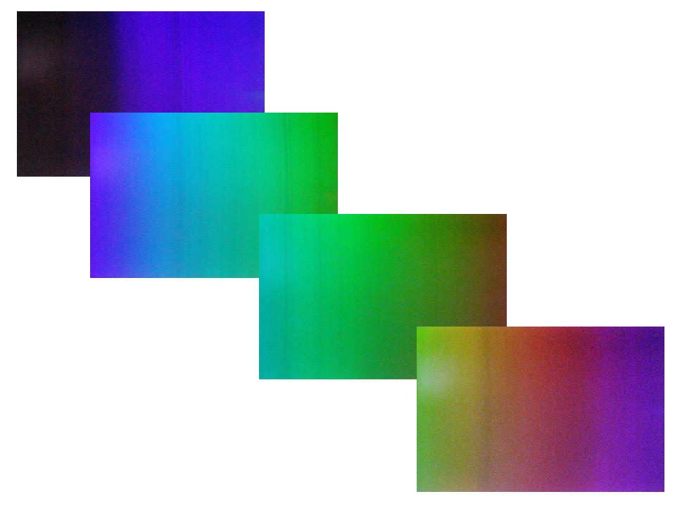
On the composite picture above, I have taken four successive images with each exposure twice the length of the previous exposure for a blue-to-red exposure sequence of 1, 2, 4, and 8 seconds, respectively. This preferential scattering is due to Rayleigh scattering by the various gas molecules in the earth's atmosphere. The amount of scatter varies inversely with the wavelength to the fourth power, which means that a small change in wavelength produces a large difference in the amount of scatter.
Because the sky color is relatively uniform and featureless, the spectrograph does not need to be tracked as the images are taken.
On the composite picture below, which is composed of 4 one-second exposures at ISO 12800, I have attempted to identify the dark vertical Fraunhofer lines, using the original Fraunhofer designations. Fraunhofer used a sequence of capital letters for the major lines and lower-case letters for the minor lines. I compared my images with examples of high-quality Fraunhofer spectra from the Internet to attempt to identify and label these lines on my composite spectrum. My identifications should be considered with the proverbial "grain of salt."
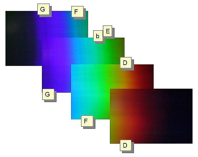
See my other web page, Blue Sky Spectra,
for my other efforts to use an unmounted CD and DVD as a primitive spectrograph to see and photograph the Fraunhofer lines of scattered sky light.
---------------------------------------------------------
Part 10 of 11: Using CD/DVD Solar Spectrograph with a "Regular" Camera Lens
The CD/DVD solar spectrograph can be used with a "regular" camera lens, rather than one of the lenses from a close-up lens set, but because there is such a large variety of lenses that could be used, my instructions necessarily will be more general. If you have an assortment of lenses available, I would recommend using a lens that can focus on objects that are close to the lens. Having a lens that can also zoom probably would be useful too.
The image below shows the adaptor I made to attach the camera to the solar spectrograph. I used the lens hood of the 52 mm diameter lens to make the connection. I used small screws to attach the black plastic coupling section to the lens hood, and then screwed the lens hood / coupling section into the front of the lens.
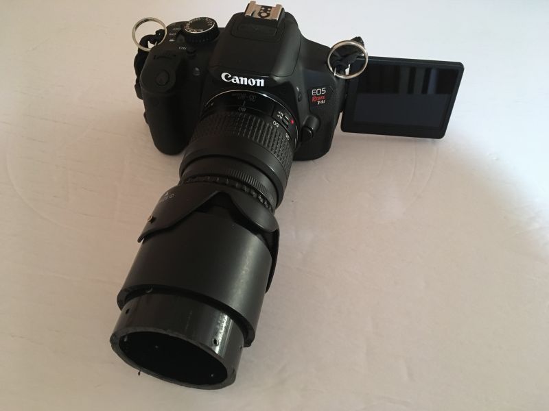
The above image shows a short (1 to 2 inch) section of plastic pipe inserted into the coupling section that is attached to the lens hood.
The images below show the CD/DVD solar spectrograph set up on my front driveway with my Canon T4i digital camera mounted on it, using a Canon EF 35-80 mm zoom lens that has a minimum focus of about only 15 inches.
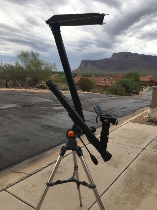
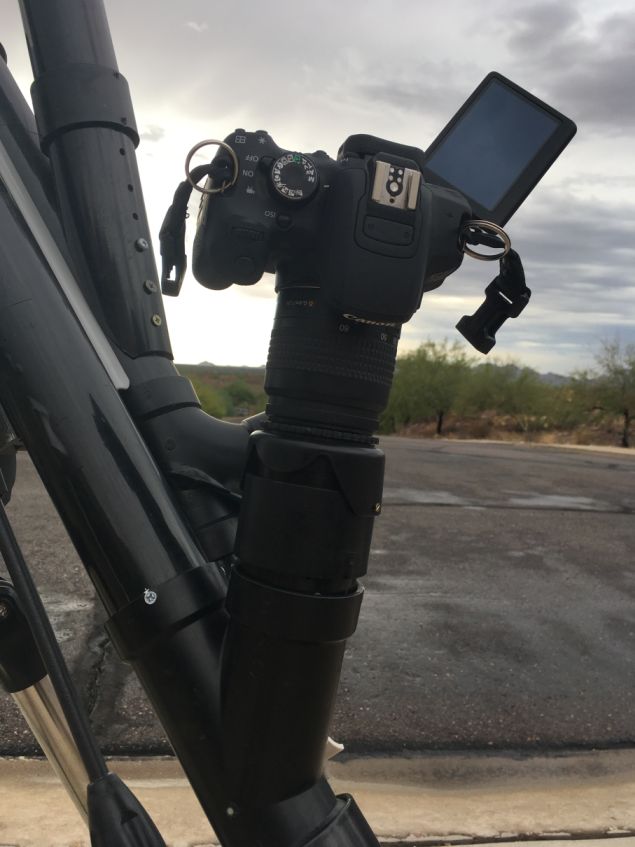
To use the CD/DVD solar spectrograph with a digital camera that is complete with its own lens, you should do the following:
(1) construct an adaptor for the camera lens by connecting a plastic junction section to the lens hood and screw the lens hood into the lens; (2) on the output end of the solar spectrograph, remove the long sections of tube, as well as the +4 diopter lens, and replace them with a relatively short (1 to 2 inch) section of black plastic tube; (3) mount the lens/camera combination on the short plastic tube via the adaptor you made in step 1; (4) on the input end of the spectrograph, if you can't achieve a focus on the dark lines in the spectrum, add some extra black plastic tube to move the slit farther from the diffraction grating; and (5) adjust both the focus and zoom until you get a fairly wide field containing a colorful image that shows crisp Fraunhofer lines.
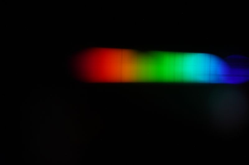
I made the full-frame image above with the telephoto lens setup that I described in this section.
---------------------------------------------------------
Part 11 of 11: Suggestions For Further Study
Suggestions for further study of stars and planets using the CD solar spectrograph (without a slit)
1. Use the +10 lens to produce a smaller (and brighter) spectrum
2. Locate the lens closer to the diffraction grating to reduce the spread of the spectrum and, therefore, make it smaller and brighter
3. Mount the CD solar spectrograph on a tracking mount to make sure that the star or planet does not move through the visual field as many frames are taken for later stacking during image processing
4. Try the tracking solar spectrograph on a star or planet using the slit configuration and repeat with the non-slit configuration to compare the results
.
Suggestions for further study of the solar spectrum using the CD or DVD with a slit
1. Obtain the noon-time spectrum with both the CD and DVD and scale the images to compare the results
2. Similar to #1, compare the spectrum of the noon-time sun with the sun partially set on the horizon to optimize the differences in the telluric (earth atmospheric) lines
3. Vary the width and/or length of the slit to optimize the solar lines that are produced
4. Mount the CD or DVD solar spectrograph on a tracking mount to make sure that the sun does not move relative to the slit and take many frames for later stacking during image processing.
---------------------------------------------------------
If you want to view my other astronomical, as well as geological and meteorological, webpages from 2009 to the present, go to the following webpage: Retirement Activities.
That page can link you to my entire Moravian College website, which includes the years before I retired.
My email address is gerencher@moravian.edu
---------------------------------------------------------
Addendum:
For measurements of my spectroscope system, and some of the theory guiding its design, see my reference at the following URL: CD and DVD Spectrograph Parameters.
.


